


Yet another repair job today, this time involving a PCB with 3 non-working columns.
Intake Information
- Case #57004 (This is just the order number for easier tracking on my end)
- Keyboard: ESNTL TKL KY-02
- Symptoms: 3 columns of switches not working (starting from F7, F8, F9)
- Service Level: 1
Unboxing and disassembly
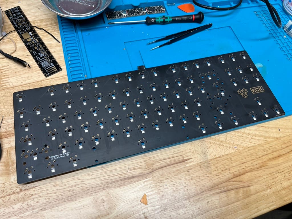
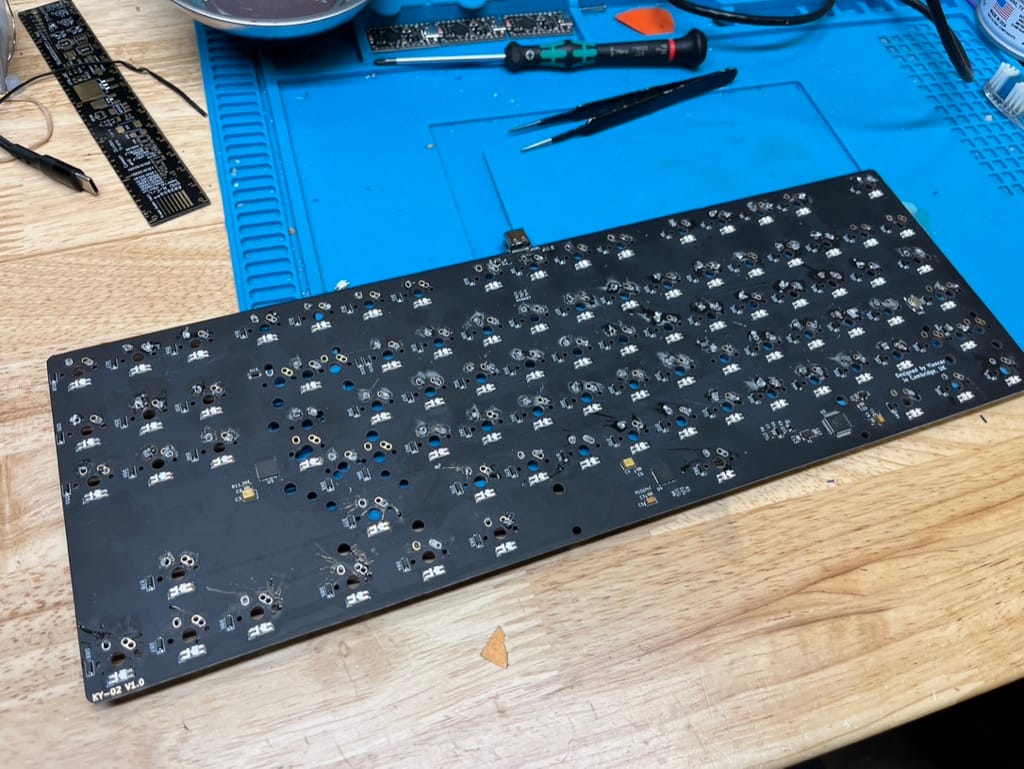
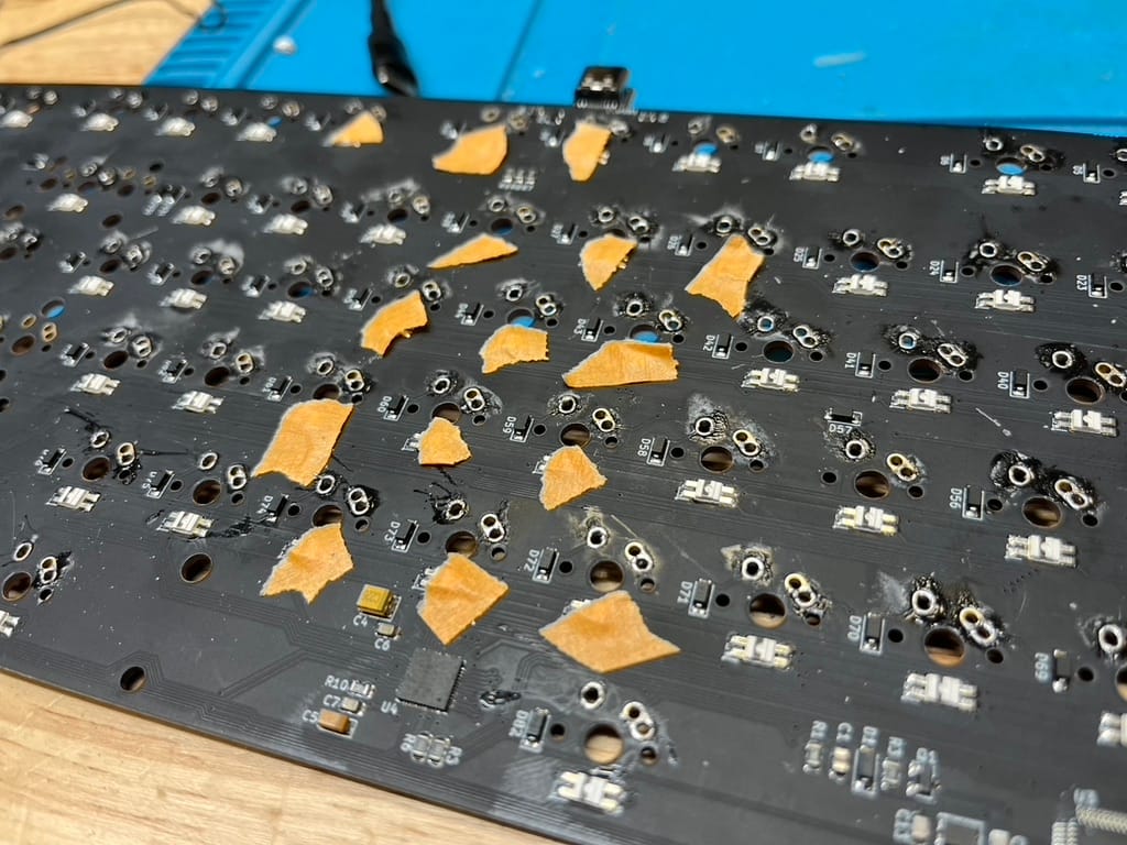
Front and back of PCB
No keyboard case this time, just the PCB, which is kinda nice, because I don't have to spend any time disassembling a case.
The soldering job on the PCB was pretty bad.
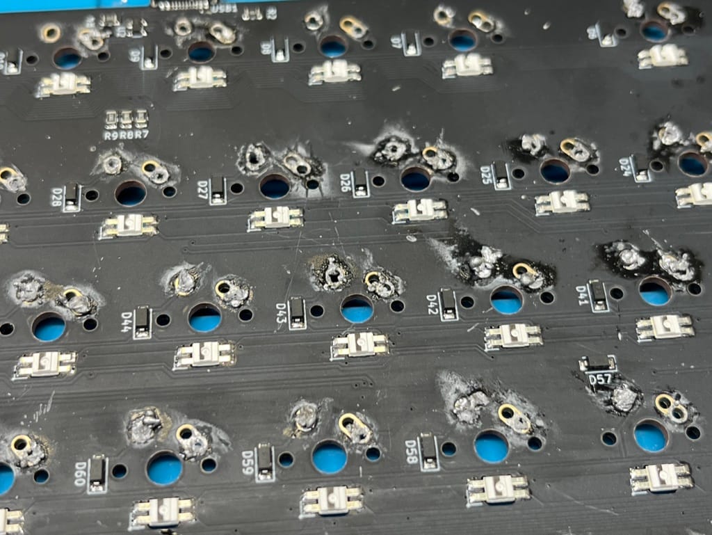
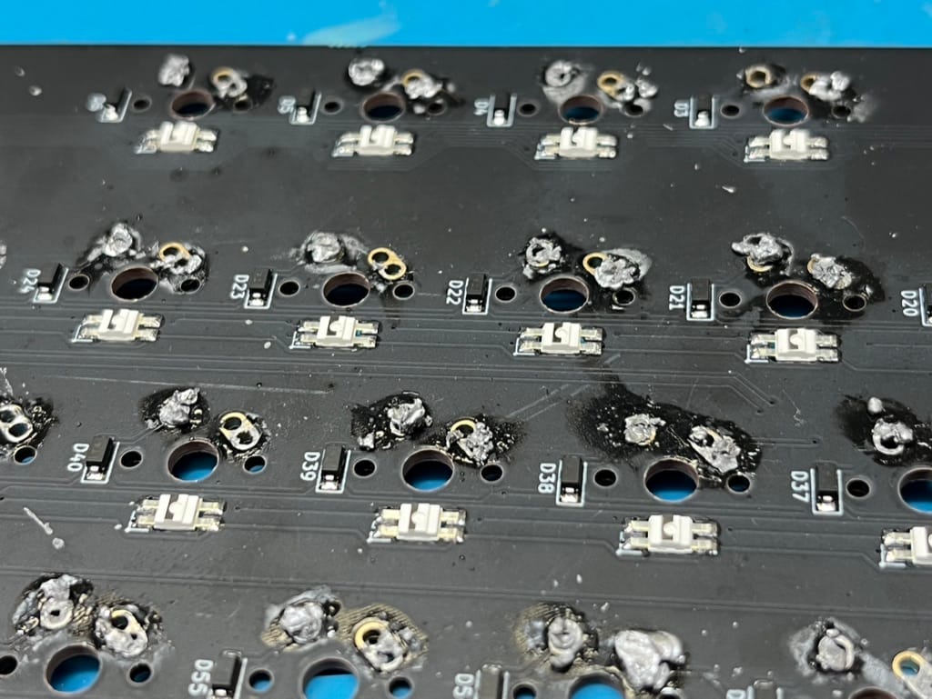
From looking at the way the solder was on the board, I would guess it's from the combination of using lead-free solder and an iron that didn't get to a high enough temperature to melt the solder properly. Lead-free solder needs higher temperatures to melt compared to the 63/37 solder I typically use and recommend.
I'll get to cleaning up the solder later.
Fixing the board
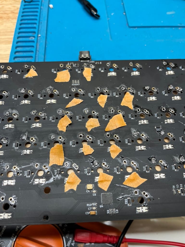
The first thing I did was plug in the board and then test all the switch locations with a pair of tweezers to confirm which spots were not working. I marked the spots with bits of orange masking tape.
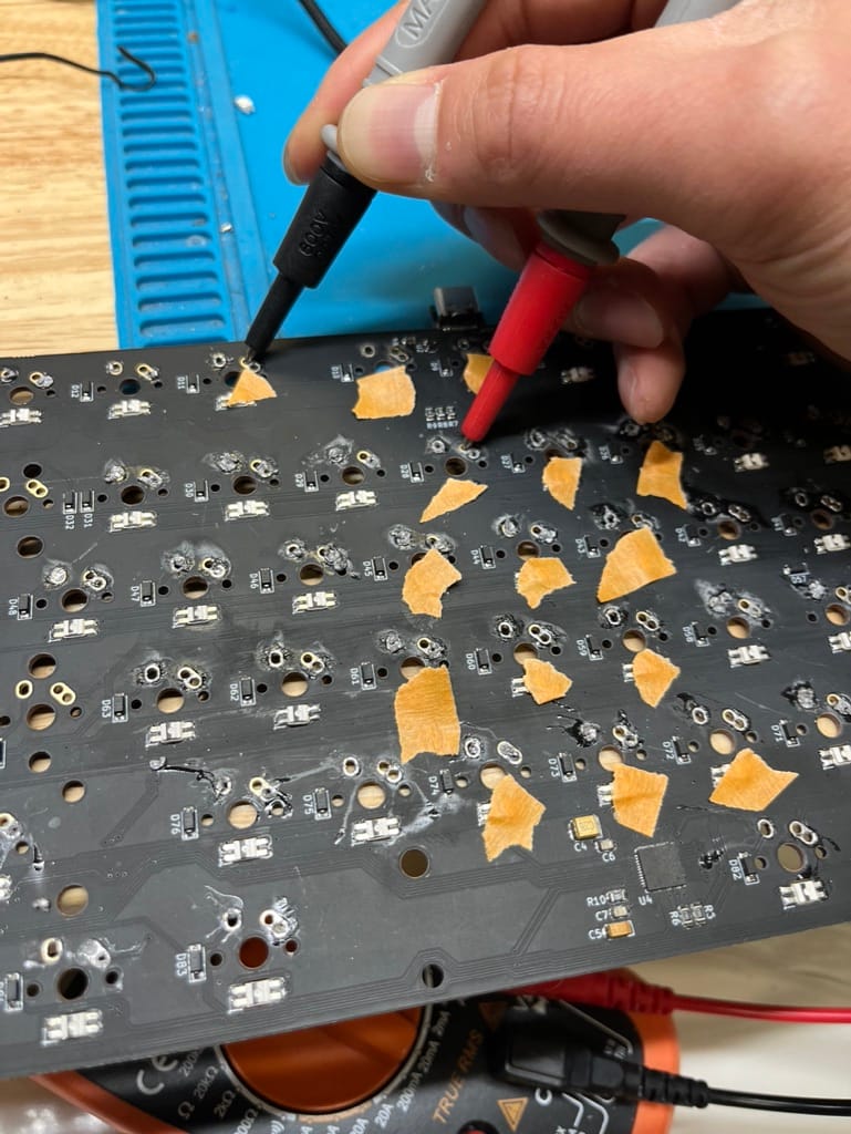
Next, I took a multimeter and set it to continuity/beep mode to check the connections between all the switches in the same column.
Here's how the switches in the same column are connected.

Testing confirmed that all the pads were still connected properly.
Microcontroller Pinouts
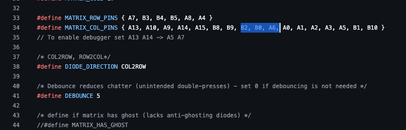
The next step was to figure out if the columns were connected to the microcontroller. I had to dig into the QMK code for the KY-02, but since it wasn't in the main QMK repository, I had to go to Yiancar's fork of QMK and find it in his ky-02 branch. I opened up the config.h for the keyboard to see which pins were mapped to the 3 columns:
From there, I pulled up the pinout for the STM32F303 (48-pin LQFP) that was on-board.
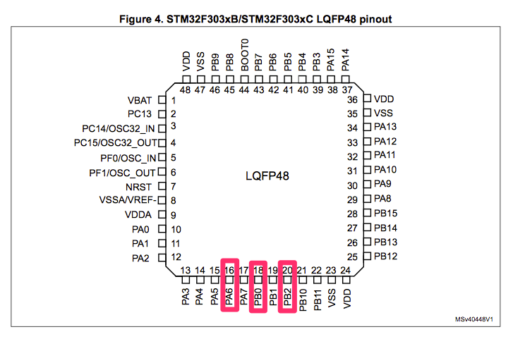
With that info, I took out the multimeter again and tested for continuity between the pins on the microcontroller with the column pads for the switches. All 3 of the connections were fine.
Firmware Issue
Since the pin connections were fine, this either meant that the 3 pins on the microcontroller were dead or there was a firmware issue. 3 dead pins simultaneously was unlikely, so a firmware issue was more likely.
I cloned Yiancar's QMK fork and checkout the ky-02 branch and tried compiling it. The build hung though due to the branch being 5 years old, and while I could figure out what was the issue with the build tools, it wasn't worth the effort. So I copied the keyboard files to the latest version of QMK and made some changes to the configuration, since the structure of things has changed a bunch in QMK in the last 5 years. A lot of it involved adding stuff to keyboards/wilba_tech/wt_rgb_backlight.c, since there was a lot of custom RGB code in there.
After compiling it and uploading it to the PCB, all 3 columns were working again. The RGB lighting wasn't 100% showing the correct colors due to my hasty port, but luckily I know Yiancar. So I sent him a message, asking if he already had a .bin file for the KY-02 handy, and he sent it over to me right away. Turns out, the person selling the PCBs used an older firmware with the wrong firmware flashed to them.
Reflashing the PCB with Yiancar's firmware build made all the RGB LEDs work properly, and I double-checked all the switch pads again for functionality.
Clean Up
Before shipping the PCB off, I couldn't just leave all that bad soldering on there. So I turned on my soldering iron to 750°F, heated up every switch pad, and used a solder sucker to remove all the solder.
All done!
If you need your keyboard fixed, check out our Keyboard Repair Service! Send us an email at shop@keeb.io and include info on what keyboard make/model it is and any relevant pictures of the damage so we can make an assessment.
If you like reading about more repairs, check out my other repair posts.


Member discussion