


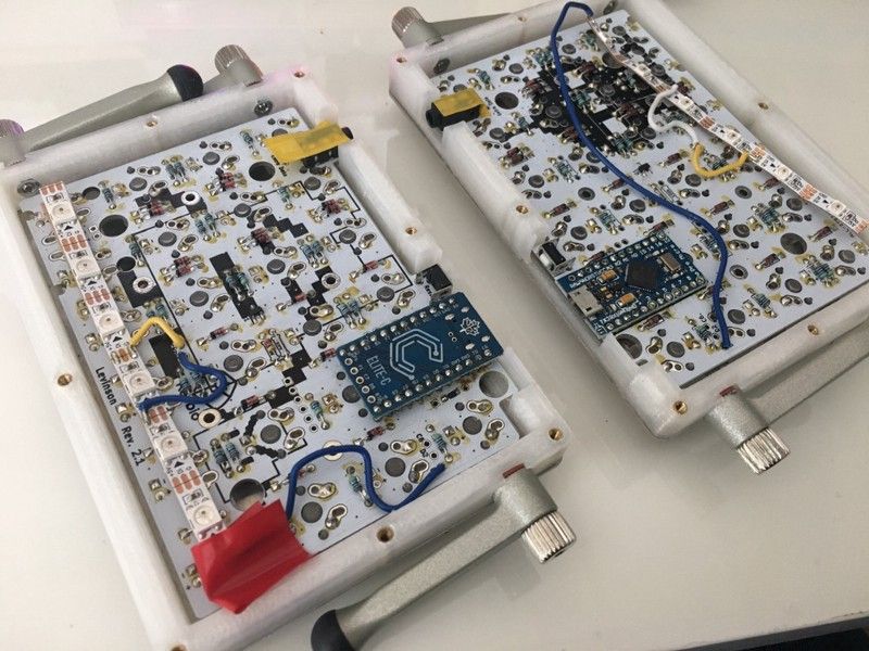
For some DIY mechanical keyboards, instead of an integrated microcontroller, a daughterboard like the Pro Micro is used. Pro Micro-based builds/PCBs are commonly found in designs for split keyboards like the Let’s Split, Quefrency, and Iris (the older Rev. 2), due to split keyboards being relatively new compared to single-piece keyboards.
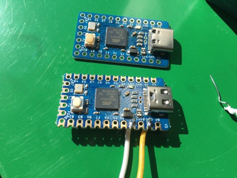
Bad Pro Micro!
The Pro Micro uses a Micro-USB port, which is a decent port, but for most of the clones out there, the Micro-USB port that was used doesn’t stay on the board very well and can be torn off.
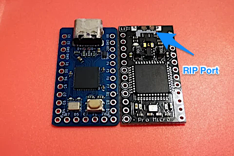
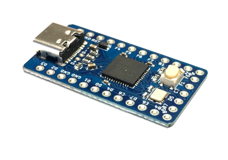
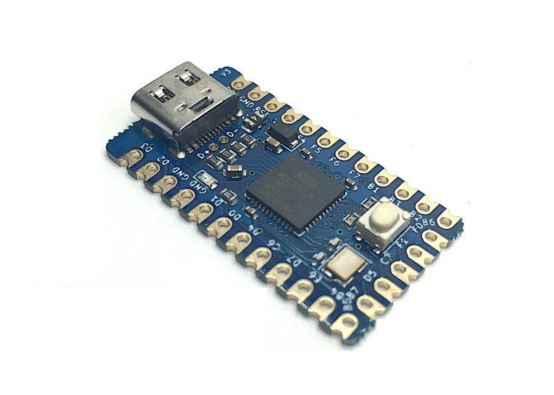
Enter the Elite-C. USB-C is being used more these days, and keyboard builders have been wanting a USB-C version of the Pro Micro to resolve the port issues with the Pro Micro. So SpaceCat Design, Maple Computing, and Keebio got together to develop the Elite-C. The goal was to produce a drop-in replacement for the Pro Micro, but with the following improvements:
- USB-C port
- DFU bootloader instead of Caterina bootloader
- More pins of the ATmega32u4 controller made available
- Reset button
Here’s a fun little video how the USB-C port of the Elite-C holds up:
Different versions
To date, there have been 3 different versions of the Elite-C. Here’s a quick summary of the different versions:
V1: Initial release, no major issues, except for Schottky diode not being soldered on properly sometimes. The diode’s SOD-123 legs were fairly small, so we switched to a SOD-123F package for V2.
V2: Since the V1 did not have an LED on there, some people mistakenly thought that their Elite-C was not working, so we added an LED in between VCC and GND to indicate that the board is getting power. A 500mA fuse was also added for protection (sorry drashna for ruining your RGB dreams). A couple of runs were done with V2.
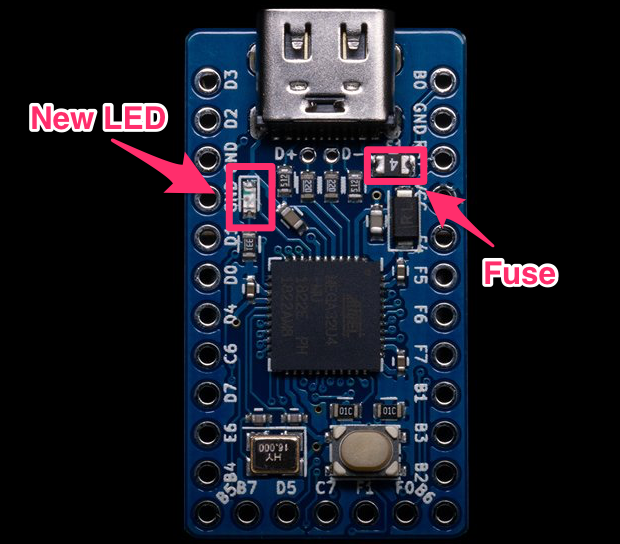
V3: For V3, we decided to play around with adding castellated holes to allow for soldering to a board with special solder pads for a lower profile build.
Signs of trouble
Problems with V1 and V2 were fairly minimal. However, with the release of V3, issues were being reported of slave halves using the V3 not working with boards like the Corne, Quefrency, etc. People tried a mix of boards using Pro Micro and Elite-C V1/V2 controllers to experiment with what would work.
Most of this discussion took place on the QMK and Keebio Discord servers, and shoutout to Yan-Fa Li for working with people to determine that there was an issue with V3. After a few reported cases, Chris (of Maple Computing) and I took a look at the schematic and that everything checked out with the Schottky, which we suspected was a possible source of the issue.
How split keyboard detection works
For a split keyboard, each half needs to know if it is the master half or the slave half. The master half will be the one that talks to the computer and sends up keystrokes, while the slave just sends its keystroke info via a TRRS cable to the master and does not talk to the computer.
To determine which half is the master, we need to figure out which half is connected via USB to the computer. Currently in QMK, the firmware used for these keyboards, this is done by reading in the VBUS pin when the board starts up. If the VBUS pin is high (close to 5V), we determine that it’s connected to the USB port and call it the master. If the VBUS pin is low (close to 0V), then we set it to be the slave.
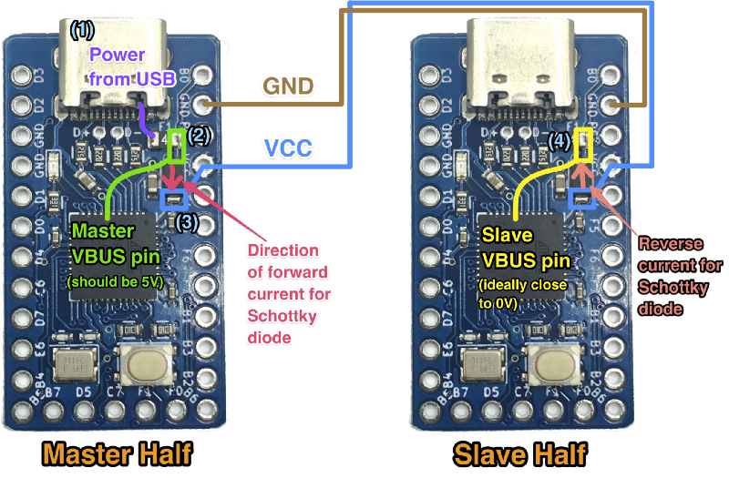
Now how we set up the circuitry on the board to allow for this method of detection to work? Let’s look at how current flows within the split keyboard.
- Power comes in from the USB port at 5V (marked in purple).
- It then goes through a fuse and at the other side, it will still be 5V (green on the master half). This is connected to the VBUS pin of the master’s ATmega32u4, which will be read in.
- Next, it goes through a Schottky diode. The purpose of a diode is to allow current to flow in one direction (from anode to cathode), but not in the reverse direction. However, the cost of this is a forward voltage drop, which varies based on diode. For the common 1N4148 diode, it’s about 0.6–0.7V, which would make VCC about 4.3–4.4V, which is a bit lower than the 32u4 ideally wants. So we used a Schottky diode, which has a lower voltage drop of 0.3–0.4V, resulting in a VCC of 4.6–4.7V.
- VCC makes its way across the TRRS cable (with negligible voltage drop if any), and then there’s a small bit of current that goes backwards through the slave’s Schottky diode from the cathode to the anode. This current is called reverse current. Hopefully, this reverse current is minimal and that the slave’s VBUS pin voltage is close to 0V.
So based off of this, our hypothesis was that the Schottky diode is the source of the issue.
Rolling up my sleeves and digging into the issue
After hearing about 4–5 reports of the issue, I decided to set aside some time to investigate it. I took a pair of brand-new, unflashed Elite-C V3s and soldered on jumper wires to join the VCC and GND pins of the two together.
Testing procedure:
- Plug USB into one of the Elite-Cs, which will simulate being the master
- Check voltage before and after the Schottky diode on both master and slave controllers
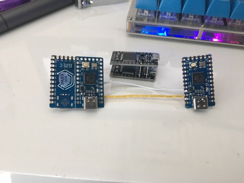
The main measurement of interest is the anode side of the slave half’s Schottky. Ideally, this should be somewhere close to 0V. Well, when I did the measurement of the ‘slave’ Elite-C V3, it was 1.1V. Hmmm…
Logic Levels
So what does 1.1V translate to when the 32u4 microcontroller reads the pin? Is it a 0 (low) or 1 (high)? This is when I had to dig through the datasheet for the ATmega32u4.
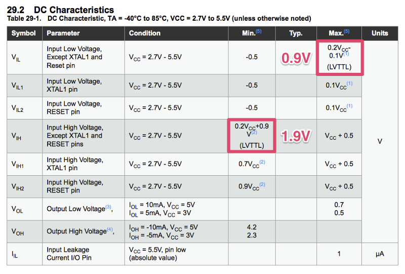
Highlighted above are the relevant values we need to take a look at. VCC is 5V in this case, so it means that 0–0.9V translates to a 0 (low), and 1.9V-5V translates to a 1 (high). Well, the reading of 1.1V I measured is in between, which is in a grey area, and it ended up getting marked as high when the read was done. As a result, the firmware thought the slave Elite-C was the master.
Not good.
But why was the voltage 1.1V in the first place? Time to dig some more.
Reading more datasheets
Before I had even setup my testing rig, I noticed that the Schottky diodes on the V2 and V3 were different. So I asked Chris for the part number of the Schottky on the V3 to see what the difference was.
The Schottky used in the Elite-C V2 is the B5817WL, here’s the datasheet for it: https://datasheet.lcsc.com/szlcsc/SK-B5817WL_C122853.pdf
Schottky used in V3 (MBR1020VL): https://datasheet.lcsc.com/szlcsc/ON-Semicon-ON-MBR1020VL_C191986.pdf
The switch of diodes from the one in V2 to the one in V3 was mainly driven by the desire for a lower forward voltage drop. Forward voltage drop is the amount that the voltage drops between one side of the diode to the other. For the 32u4, since the best operating range is 4.5V or higher, and the input voltage to the USB port is 5V, this means that you want a voltage drop of 0.5V (500mV) or lower.
Here’s the forward voltage drops of the two different Schottkys:
- V2: 450mV @ 1A
- V3: 340mV @ 1A
The other thing that was overlooked though while assessing the diode swap is the reverse current, which is basically the amount of current that goes backwards towards the USB port.
Here’s the reverse current numbers at 5V for each diode, as seen from the charts below:
- V2: 5uA
- V3: 40uA
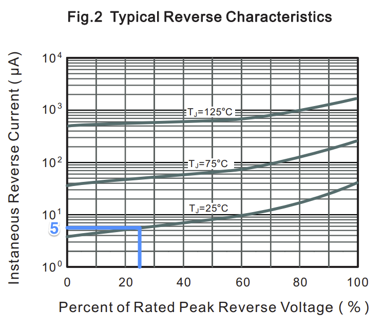
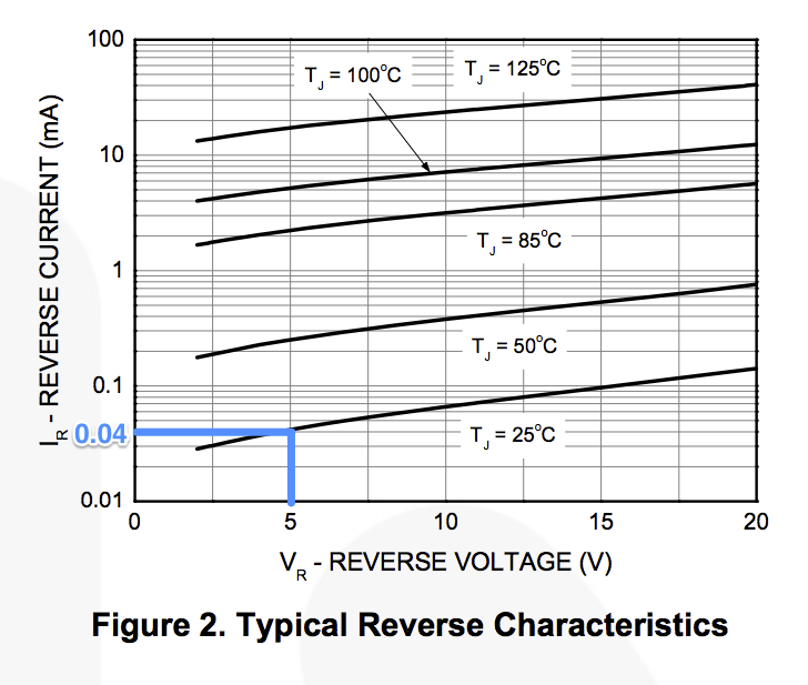
The V3 Schottky diode has a much greater reverse current than the one for the V2. Aha, the source for the higher anode voltage has been found! We also consulted with our friend gondolindrim (EE wizard working on his PhD), who confirmed with us that the tradeoff for a lower forward voltage drop is an increase in reverse leakage current.
Okay, so what’s next?
What do we do now?
Now that we know what the problem is and where it came from, how do we fix it?
One option is a hardware fix by going to all of the Elite-C V3s and swapping out the Schottky diode. Yeah, not going to happen, that’s way too much work. Better to fix that with a new version (to be discussed later).
Another option is to make a fix on the firmware side and change the method of master/slave detection. Conveniently, zvecr was already working on a new detection method to help with support for ARM-based boards, like the Proton C.
GitHub qmk/qmk_firmware: ARM split - detect USB to select master/slave #6424
I won’t go too much into detail on this detection method, but basically it waits about a half second after startup and checks if a USB address has been enumerated to the controller or not.
A few of us collaborators of the QMK Firmware reviewed and tested the new option, signed off on it, and then it got merged in. So to use the new detection method (which does not rely on the Schottky diode), in config.h of your keymap, add the following line and reflash the Elite-C V3:#define SPLIT_USB_DETECT
This line actually doesn’t do anything for some split boards like the Corne, as they don’t use the split_common framework, where the support for this new option was added in. We’re (QMK collaborators) are currently working on the issue and trying to get non split_common boards to transition over.
This USB detection method may actually become the default in the future, as we’ve been having talks about it.
Elite-C V3.1
Elite-C V3.1 was already in production while we discovered this issue, but fortunately, the components weren’t populated on the boards yet, so Chris was able to have the PCB fab switch the Schottky diode specified. Here’s what else the V3.1 brings:
- Matte black PCB instead of blue
- LED with resistor to make it dimmer, because people were complaining about the LED being too bright
- Shorter reset button, because sometimes a switch pin would collide with it
Well, hopefully some of what was talked about above made sense, I know it’s quite a bit to digest. But maybe you understand a little bit more about what goes on in debugging electronics. Despite having done design for a while now, there’s always new mistakes to be made.

Member discussion