


So you've got a brand new keyboard PCB, but you'd like to make it hotswappable? No problem, you've come to the right place with this awesome guide!
You'll find out how to select and install Mill-Max hotswap sockets into your PCB, so can you start swapping out switches anytime you'd like.
We've also got a video tutorial available as well:
Prerequisites
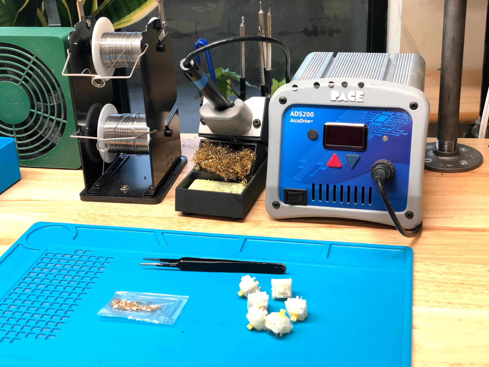
You'll need the following items for socketing your keyboard PCB:
- Soldering iron
- Solder - Thinner solder (0.020"/0.5mm or thinner) is preferred
- Mill-Max sockets
- Switches - At least 1, but using 4-6 will speed the process a bit. It also helps to use cheap switches in case you accidentally get solder into the socket
- Tweezers
If you need some recommendations on what soldering iron and solder to get, visit our recommendations page: Recommended Soldering Tools
Compatibility
Mill-Max sockets are compatible with most MX-style switches, but some switches have one leg that is much wider than the other (like Kailh Pro switches) that are hard to fit into the socket.
Mill-Max sockets can fit onto Choc switches, however, most PCBs designed for Chocs have switch pad holes that are too small for the sockets to fit into them.
Selecting Mill-Max Sockets
There are a few different varieties of Mill-Max sockets that can be used for keyboard switches. The main factors you should consider are the tail length and shoulder height above the PCB.
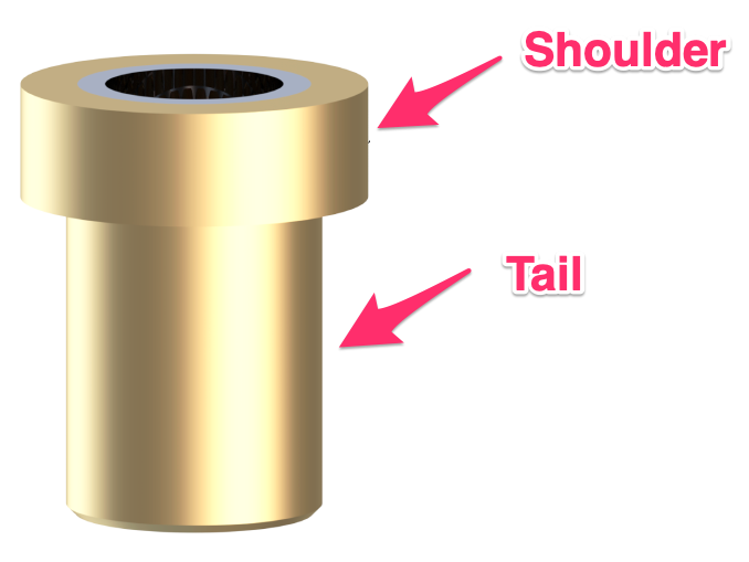
Tail length
This is the bottom length of the socket. Having a longer length makes it easier to solder to the board without getting solder into the socket. If you are better skilled at soldering, you can go with a shorter length. If you are not sure, then go with a longer length.
The -X portion of the Mill-Max model number refers to the tail length. A smaller number indicates a shorter length, while larger numbers indicate a longer length.
Hitting the bottom part of a case with longer length sockets is usually not an issue unless the case has very tight dimensions.
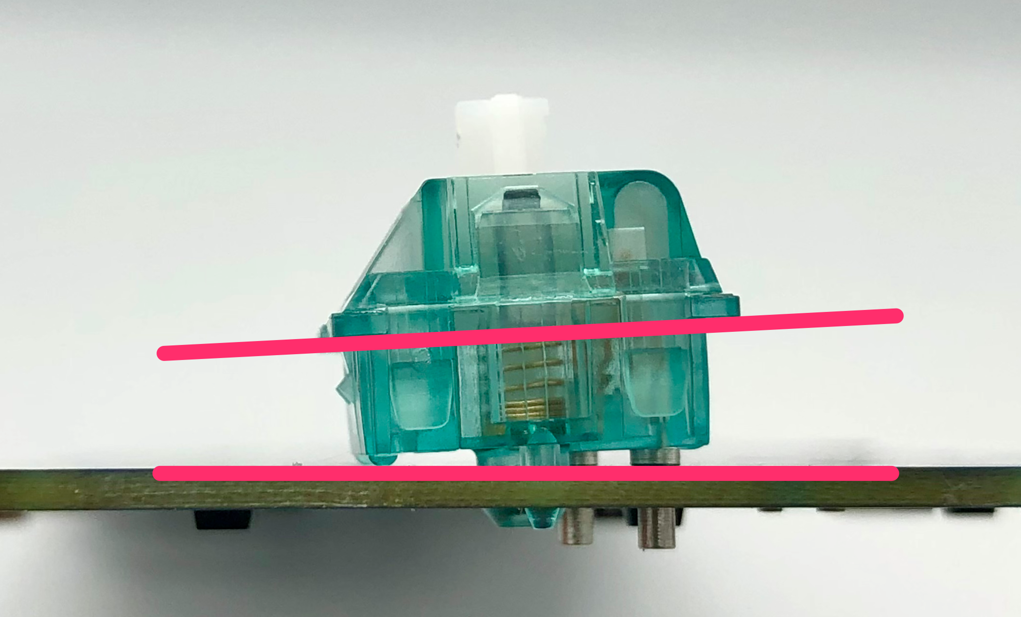
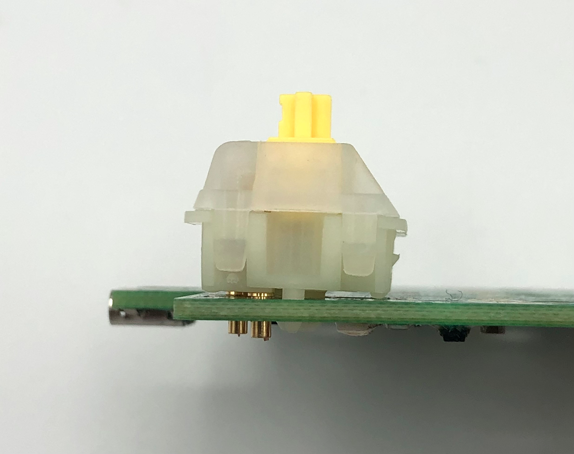
Shoulder Height
The shoulder height is the amount of socket that sits above the PCB. A lower height is better, as this allows the switch to be more flush with the PCB and making it sound better. Also, if not using a switch plate, using sockets that have a tall shoulder height will cause the switch to be angled.
Mill-Max Socket Comparison
Here's a list of the sockets, ordered by cost, from lowest to highest.
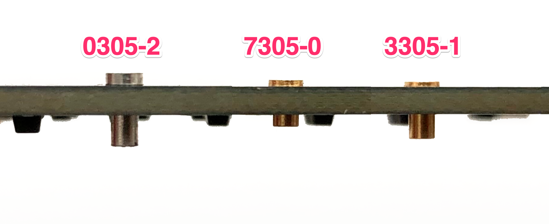
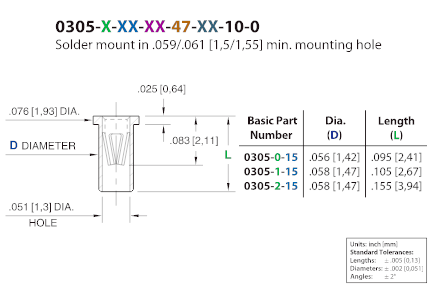
Mill-Max 0305-2
The 0305-2 are the cheapest sockets available, and they have a long tail but a tall shoulder height above the PCB of 0.64mm. The tin-plated ones of these are typically sold.
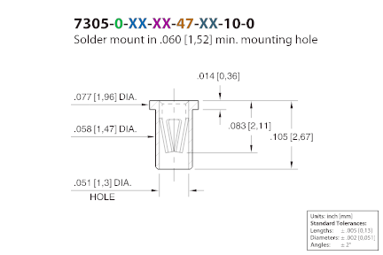
Mill-Max 7305-0
The 7305-0 are usually gold-plated, and they have a short top height of 0.36mm, but a short tail length. You need to be careful to not get solder into the socket when soldering these.
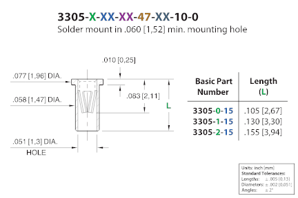
Mill-Max 3305-1
These were developed more recently and are the best of both worlds, as they combine the long tail of the 0305-2 and the short shoulder height of the 7305-0. The shoulder height of 0.25mm is actually thinner than that of the 7305-0.
Putting the Sockets on the Switches
While you can insert the sockets directly into the PCB, it can be a bit difficult to line up the sockets into the switch pads on the PCB.
A better way is to take tweezers and put the sockets on to a switch.
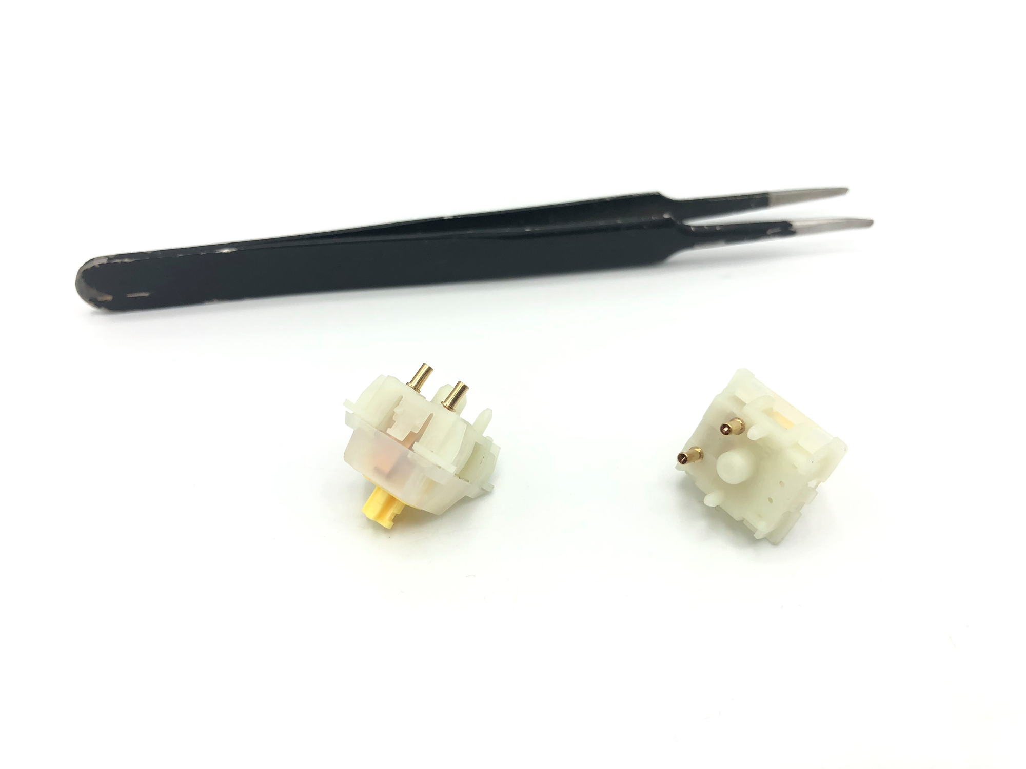
Then insert the switch/socket combo into the PCB.
Soldering the Sockets
After you've inserted the switch/sockets into the PCB, you'll solder the sockets to the switch pads.
First, take your soldering iron and heat up both the switch pad and socket at the same time.
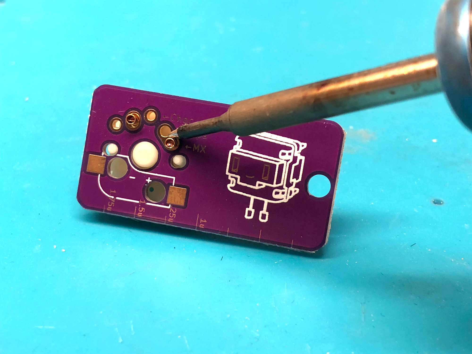
Then add solder to the joint. You may find it helps to add a bit of solder to the iron initially to get the solder to flow around the socket.
Keep the soldering iron at the joint for several seconds to allow it to flow around the socket fully.
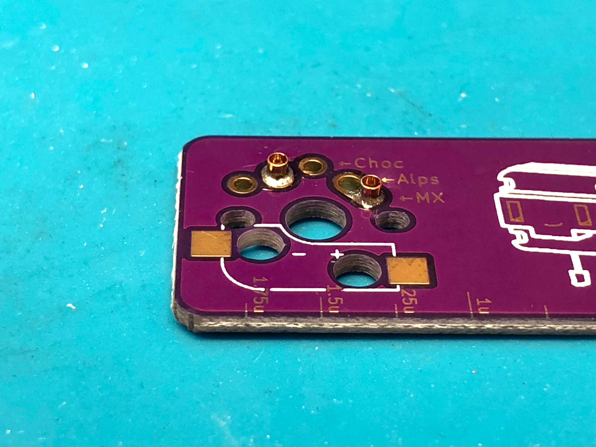
This is what the joint should look like afterward:
Things to be aware of
Be careful to not get solder into the socket. This will usually cause the switch to get stuck in the socket and can damage the socket. If you get solder into the socket, desolder the socket, remove as much solder as you can from the pad, and try again with a new Mill-Max socket.
Sometimes, you will find that after soldering the socket in, it wasn't inserted deep enough into the PCB. To fix this, clean any solder off of your soldering iron. Next, heat up the socket from the top of the PCB for a few seconds. Then, push down on the socket to reseat it fully into the pad.
Be sure that the solder has melted before pushing down, since otherwise, the pad on the bottom side of the PCB may get ripped off.
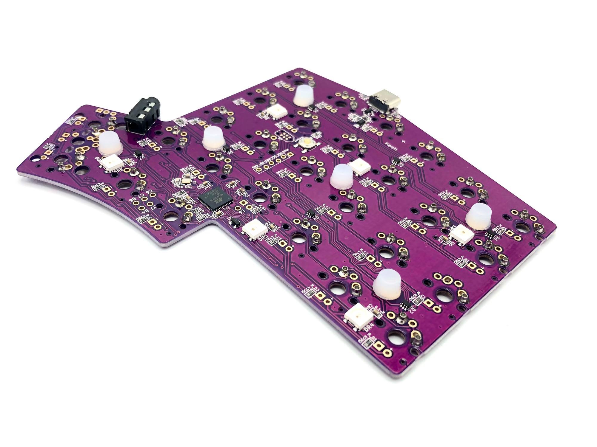
Supporting your PCB
Once you've installed Mill-Max sockets into your PCB, there's a chance that the PCB will come off of the switches if anything pushes down on the PCB. This commonly occurs if you have a rotary encoder installed that can also be pushed down as a switch.
To prevent this from happening you'll need to add support underneath your PCB. One thing you can use is FLAHNS, which are silicone bumpers that you can apply to the bottom of the PCB.
A good spacing for the bumpers is about one for every 4-5 switches, and one under each encoder if you have them.
Best of luck with making your keyboard PCB hotswappable, you got this! 😄


Member discussion